All Ireland Water & Wastewater Expo
The All-Ireland Water & Wastewater Expo is a conference and exhibition designed to bring together key stakeholders from the municipal, industrial and domestic water & wastewater community together to discuss and debate the key issues facing our water & wastewater sector.
Water Pipeline Solutions
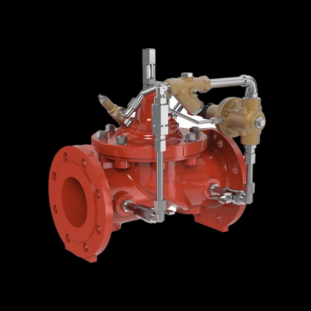
Find the perfect pressure reducing valve for your water distribution needs and ensure steady, safe operation

CLA-VAL PRV
IPL group has a comprehensive portfolio and years of experience in delivering sustainable and affordable solutions for water networks.
View ProductsWater Pipeline Solutions
Find the perfect pressure reducing valve for your water distribution needs and ensure steady, safe operation
Over five decades of expertise
Local and International
Quality, Safety, Environmental
Comprehensive service commitment


Practical skills for real-world water networks.
Using our state-of-the-art flow rig, we deliver immersive and hands-on training experiences for local authorities and industry professionals by simulating a real-world water network.
Tailored Solutions for Complex Challenges
With over 50 years in the Irish water industry, IPL group has gained a reputation for providing innovative products and effective custom-designed solutions. We pride ourselves on understanding our customers' unique needs and setting new standards in the industry.
Global Expertise
Through our network of international partners, we advise on the latest advancements and developments, providing custom-designed solutions that meet global best practice.
Custom Design
We provide tailored solutions for key areas, including water filtration (Hawle Optifil), flow and pressure management (Cla-Val), liquid analytics (Kuntze & Sigrist), and monitoring & control (Datataker & Technolog).
Dedicated Team
Our experienced team is committed to ensuring you receive an informed and courteous service every time.
Reliable Products for Network Performance
Our products are designed to ensure the integrity and longevity of your infrastructure. With a focus on quality assurance and lasting performance, we are a trusted partner in maintaining sustainable water networks.
Quality & Assurance
We offer complete supply chain transparency and extended manufacturer warranties, giving you confidence through vital stage auditing from factory production to integrated network performance.
Active Products
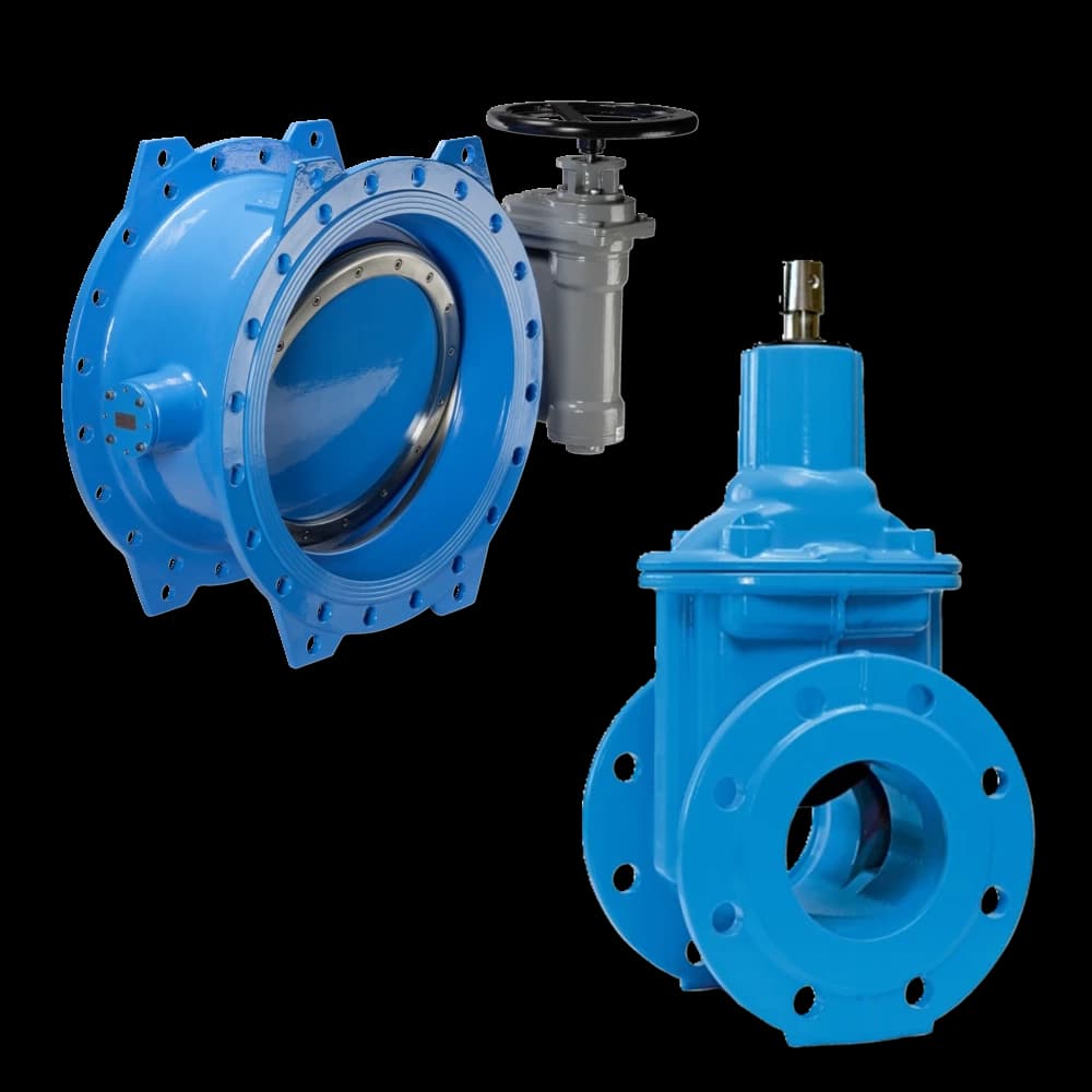
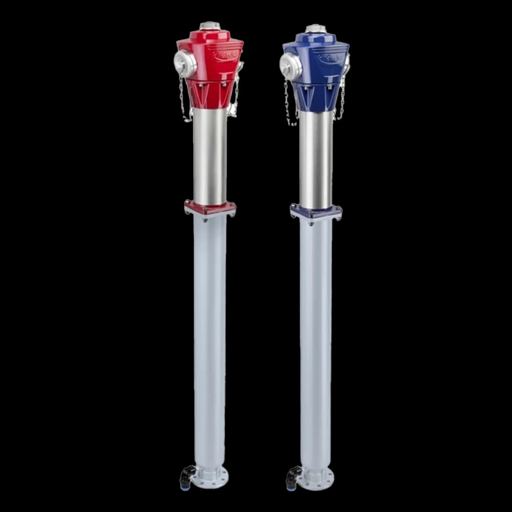
Our portfolio includes leading European brands such as Hawle, with their low-torque-operating sluice valves, butterfly valves, air valves & fire hydrants.
Passive Products
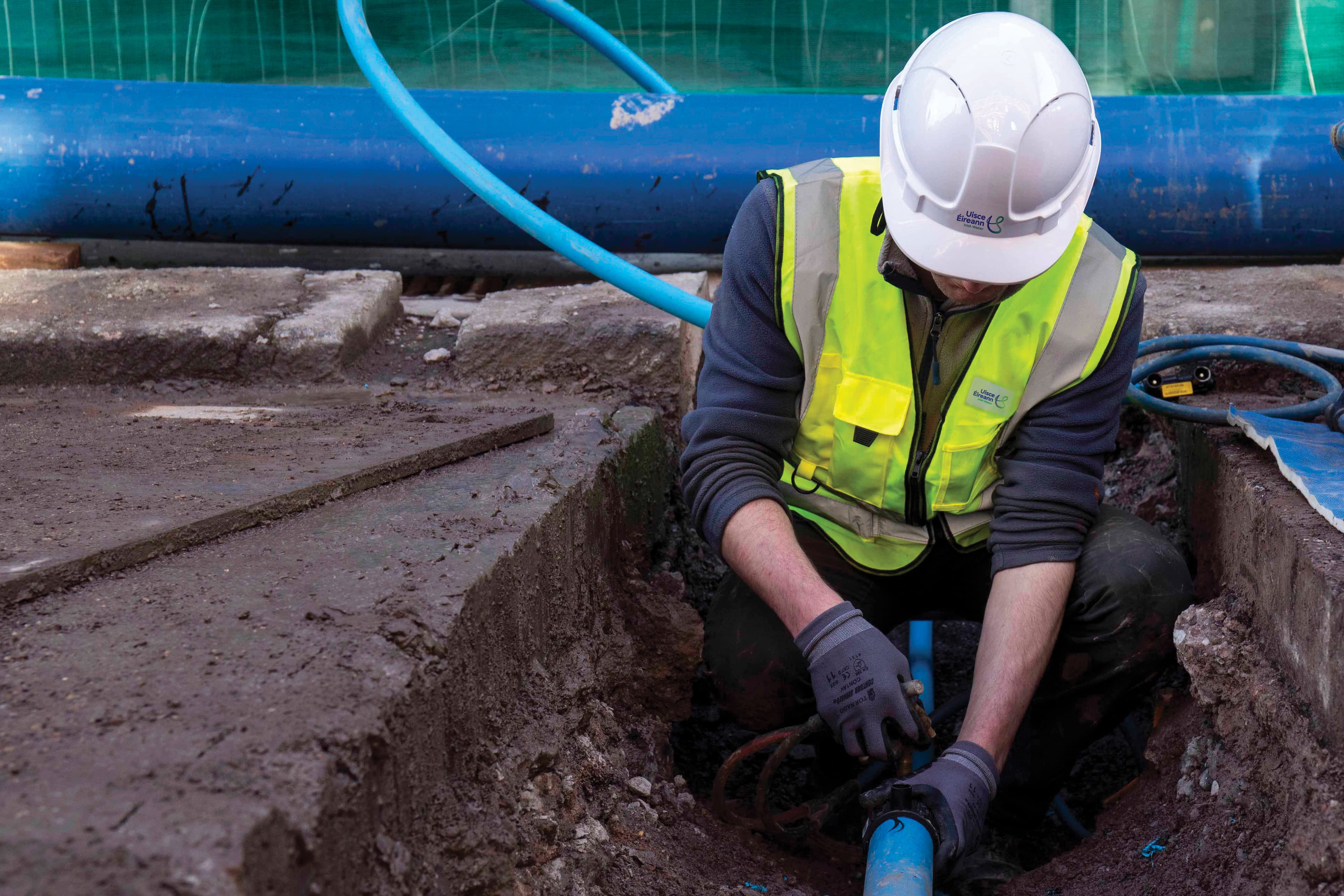
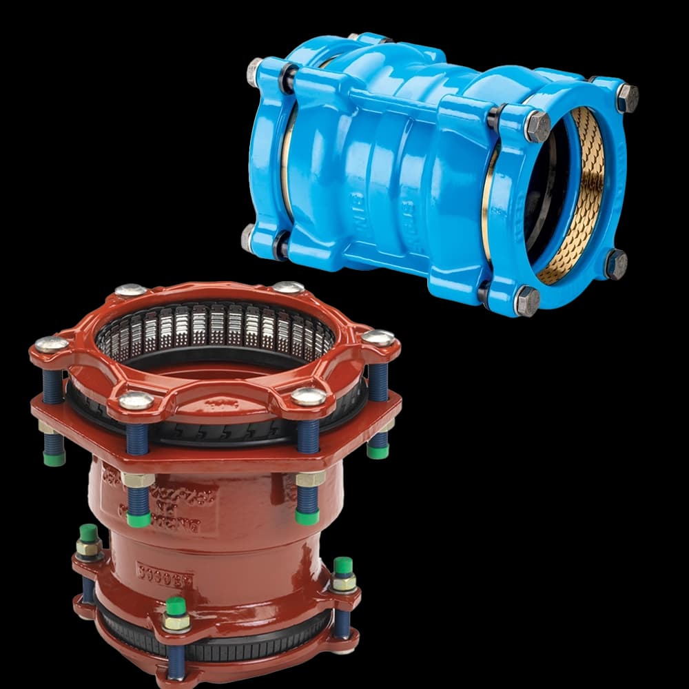
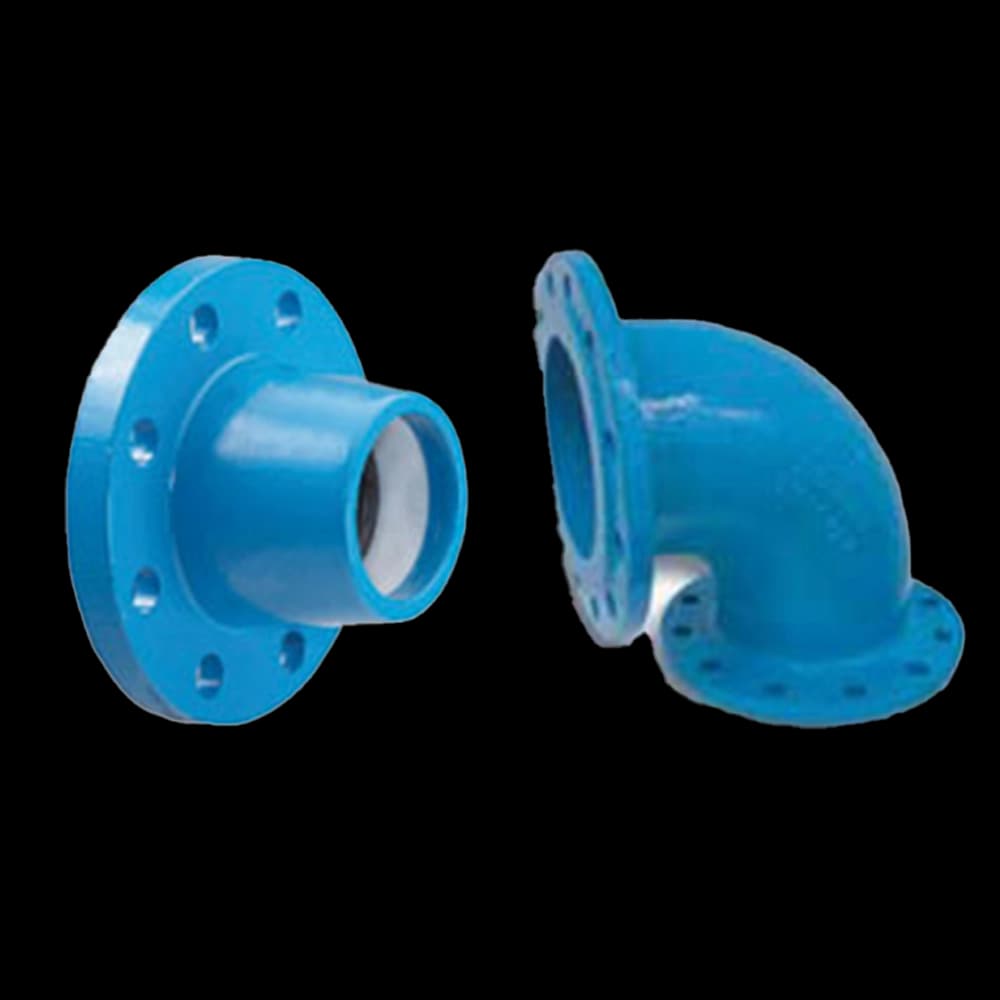
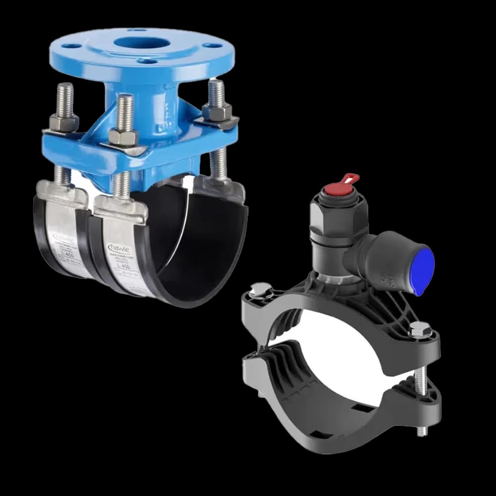
We also provide an extensive catalogue of competitively priced passive products, including restraint pipe couplings & flange adaptors, epoxy-coated flanged pipe fittings, and a full range of pipeline repair products.
Intelligent Solutions for a Smarter Network
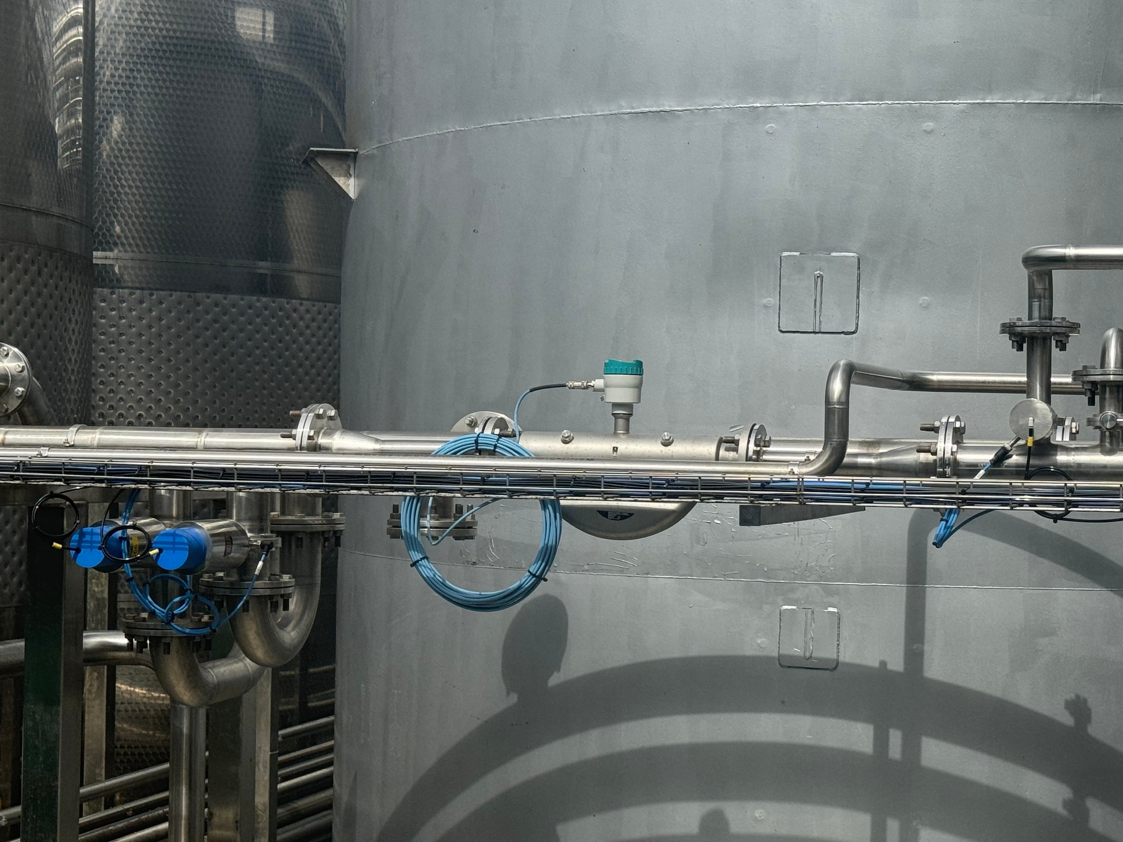
We partner with industry leaders like Siemens, Technolog, and Cla-Val to deliver next-generation solutions for real-time measurement and monitoring. Our advanced control systems provide the data and insights you need to make intelligent decisions and effectively manage your network.
Data-Driven Decisions
We partner with industry leaders like Siemens, Technolog, and Cla-Val to deliver next-generation solutions for real-time measurement and monitoring. Our advanced control systems provide the data and insights you need to make intelligent decisions and effectively manage your network.
Optimised Performance
Improve day-to-day network performance and emergency response capabilities with solutions that help you reduce burst frequency and proactively manage assets.
Water Conservation
Effectively identify unaccounted network losses and leakage to improve water conservation and operational efficiency.


