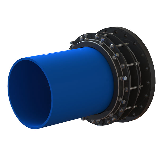
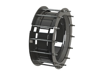
Central body
Carbon steel central body conveniently built in order to allow a perfect insertion of the gasket inside its dedicated conical seat.
Compression ring
Carbon steel compression followers which allow compression of the gasket onto the pipe
surface upon tightening the bolts.
Gasket
Truncated-cone sealing gasket which can be perfectly inserted between the central body of the coupling and the circumference of the pipe. It allows a complete hydraulic seal and a 30 mm tolerance range on the pipe OD.
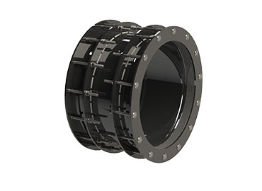
Bolt holes
Round or square holes for the bolt insertion.
Compression bolts
The compression bolts allow the approaching of the compression flanges and the consequent
compression of the gasket onto the pipe.
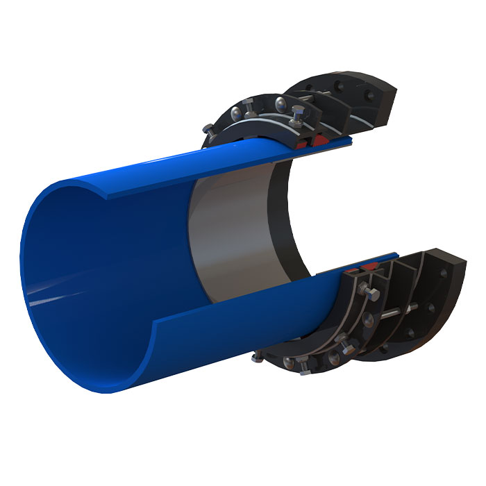
Radial set of pull-out resistance grippers
Manufactured in C40 tempered steel, they allow the total locking of the pipe. End restraint
grippers, which can be used on PE, steel, DCI and PVC pipe lines, guarantee a pull-out resistance action and their special design allows an easy assembly and disassembly of the coupling without damaging the Rilsan coating.
End restraint containing ring
Manufactured in carbon steel, optimizes the pull-out resistance action, also avoiding the rotation of the grippers during the tightening phase.
Connection flange(Flanged version)
Carbon steel flange.
Separate bolts version
The bolts tightening is independent in order to improve the coupling centering and the performances of the gasket.
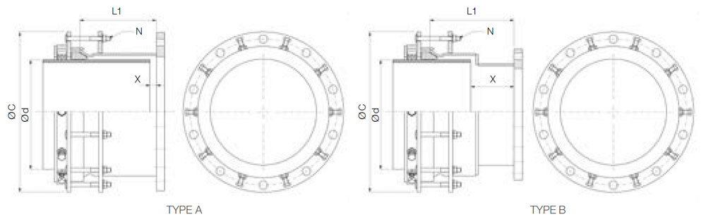
MULTIGRIP MGR-F FLANGE ADAPTOR RATED HYDRAULIC SEALING AND END RESTRAINT SYSTEM
|
DN
|
Ø d
|
Flange DN
|
Flange PN
|
Type
|
L1
|
Max. External Dimension Ø C
|
Compression Bolts
|
Gap X
|
Weight
|
|
Min.
|
Max.
|
Quantity N
|
Max.
|
Min.
|
|
350
|
340
|
370
|
350
|
6-10-16
|
A
|
296
|
560
|
9
|
220
|
25
|
106
|
|
360
|
390
|
6-10-16
|
580
|
109
|
|
400
|
385
|
415
|
400
|
6-10-16
|
600
|
122
|
|
415
|
445
|
6-10-16
|
640
|
127
|
|
450
|
440
|
470
|
450
|
6-10-16
|
660
|
12
|
143
|
|
465
|
495
|
6-10-16
|
680
|
148
|
|
500
|
490
|
520
|
500
|
6-10-16
|
720
|
160
|
|
515
|
545
|
6-10-16
|
740
|
165
|
|
545
|
575
|
6-10-16
|
B
|
326
|
788
|
14
|
250
|
170
|
178
|
|
600
|
595
|
625
|
600
|
6-10-16
|
A
|
296
|
808
|
15
|
220
|
25
|
203
|
|
615
|
645
|
6-10-16
|
828
|
207
|
|
700
|
695
|
725
|
700
|
6-10-16
|
908
|
18
|
238
|
|
720
|
750
|
6-10-16
|
933
|
255
|
|
800
|
785
|
815
|
800
|
6-10-16
|
998
|
290
|
|
795
|
825
|
6-10-16
|
1008
|
292
|
|
825
|
855
|
6-10-16
|
1038
|
315
|
|
900
|
885
|
915
|
900
|
6-10-16
|
1098
|
342
|
|
900
|
930
|
6-10-16
|
1113
|
20
|
345
|
|
930
|
960
|
6-10-16
|
1143
|
366
|
|
1000
|
985
|
1015
|
1000
|
6-10-16
|
1198
|
22
|
403
|
|
1000
|
1030
|
6-10-16
|
1213
|
407
|
|
1030
|
1060
|
6-10-16
|
1243
|
460
|
|
1200
|
1185
|
1215
|
1200
|
6-10-16
|
1398
|
24
|
556
|
|
1205
|
1235
|
6-10-16
|
1418
|
561
|
|
1240
|
1270
|
6-10-16
|
1453
|
580
|
|
1400
|
1385
|
1415
|
1400
|
6-10-16
|
1598
|
-
|
|
1405
|
1435
|
6-10-16
|
1618
|
-
|
|
1445
|
1475
|
6-10-16
|
1658
|
30
|
-
|
|
DN
|
Ø d
|
Flange DN
|
Flange PN
|
TYPE
|
L1
|
Max. External Dimension Ø C
|
Compression Bolts
|
Gap X
|
Weight
|
|
Min.
|
Max.
|
Quantity N
|
Max.
|
Min.
|
|
350
|
340
|
370
|
350
|
6-10-16
|
A
|
296
|
560
|
9
|
220
|
25
|
132
|
|
360
|
390
|
6-10-16
|
580
|
136
|
|
400
|
385
|
415
|
400
|
6-10-16
|
600
|
150
|
|
415
|
445
|
6-10-16
|
640
|
157
|
|
450
|
440
|
470
|
450
|
6-10-16
|
660
|
12
|
178
|
|
465
|
495
|
6-10-16
|
680
|
183
|
|
500
|
490
|
520
|
500
|
6-10-16
|
720
|
208
|
|
515
|
545
|
6-10-16
|
740
|
213
|
|
545
|
575
|
6-10-16
|
B
|
326
|
788
|
14
|
250
|
170
|
216
|
|
600
|
595
|
625
|
600
|
6-10-16
|
A
|
296
|
808
|
15
|
220
|
25
|
261
|
|
615
|
645
|
6-10-16
|
828
|
265
|
|
700
|
695
|
725
|
700
|
6-10-16
|
908
|
18
|
278
|
|
720
|
750
|
6-10-16
|
933
|
291
|
|
800
|
785
|
815
|
800
|
6-10-16
|
998
|
330
|
|
795
|
825
|
6-10-16
|
1008
|
332
|
|
825
|
855
|
6-10-16
|
1038
|
342
|
|
900
|
885
|
915
|
900
|
6-10-16
|
1098
|
355
|
|
900
|
930
|
6-10-16
|
1113
|
20
|
375
|
|
930
|
960
|
6-10-16
|
1143
|
440
|
|
1000
|
985
|
1015
|
1000
|
6-10-16
|
1198
|
22
|
490
|
|
1000
|
1030
|
6-10-16
|
1213
|
494
|
|
1030
|
1060
|
6-10-16
|
1243
|
510
|
|
1200
|
1185
|
1215
|
1200
|
6-10-16
|
1398
|
24
|
-
|
|
1205
|
1235
|
6-10-16
|
1418
|
-
|
|
1240
|
1270
|
6-10-16
|
1453
|
-
|
|
1400
|
1385
|
1415
|
1400
|
6-10-16
|
1598
|
-
|
|
1405
|
1435
|
6-10-16
|
1618
|
-
|
|
1445
|
1475
|
6-10-16
|
1658
|
30
|
-
|
The data concerning the min. and max. gap is calculated on the minimum outside diameter of the product's range
All end restraint fittings installed on pe Or pressure PVC Pipes must be integrated with an internal reinforcing liner provided or approved by noVA SIRIA.
This chart is for indicative purposes. Nova Siria srl can vary the indicated standards (tolerance range, dimensions and materials) according to specifications requested by Customers or to designing needs.
NOVA SIRIA end restraint fittings are suitable for the following pipes: steel, ci/DI, PE, pressure PVC.
If you would like more information on this product, please feel free to call us on
+353 (0) 41 983 2591
or contact us by filling in the contact form below and we will get back to you.
Thank you.