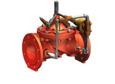
The CLA-VAL 40-01 is typically installed where water supply to a system (inlet to a reservoir, industrial users, etc.) must be limited to a maximum flow rate.
The Orifice Plate Assembly may be fixed directly to the main valve outlet flange, however, better control is obtained if it is installed in stabilized flow conditions downstream of the valve.
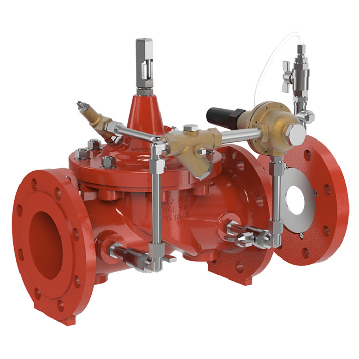
Included accessories:
Valve position indicator X101
Gauge cock CSA-12, Rp 1/2" (upstream)
Pressure gauge [0-16 bar]
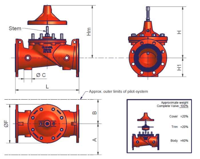
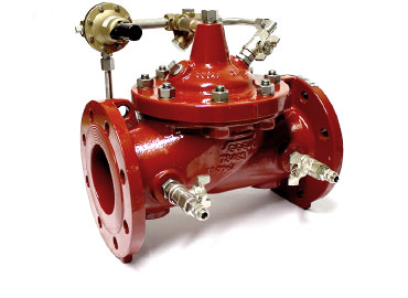
CLA-VAL 50-01 Technical Specifications
| Flanged(mm) |
DN50 |
DN65 |
DN80 |
DN100 |
DN125 |
DN150 |
DN200 |
DN250 |
DN300 |
DN350 |
DN400 |
DN450 |
DN500 |
DN600 |
| L |
230 |
290 |
310 |
350 |
400 |
480 |
600 |
730 |
850 |
980 |
1100 |
1200 |
1250 |
1450 |
| F |
145 |
170 |
170 |
235 |
295 |
295 |
400 |
510 |
600 |
712 |
712 |
712 |
900 |
900 |
| H |
195 |
225 |
230 |
305 |
365 |
375 |
460 |
547 |
695 |
821 |
821 |
900 |
1035 |
1035 |
| H1(PN10) |
82.5 |
93 |
100 |
110 |
125 |
142.5 |
170 |
200 |
227.5 |
252.5 |
282.5 |
325 |
370 |
430 |
| H1 (PN16) |
82.5 |
93 |
100 |
110 |
125 |
142.5 |
170 |
200 |
227.5 |
260 |
290 |
325 |
370 |
430 |
| H1 (PN25) |
82.5 |
93 |
100 |
117.5 |
135 |
150 |
180 |
212.5 |
242.5 |
277.5 |
310 |
335 |
370 |
430 |
| Hm |
255 |
295 |
300 |
390 |
470 |
480 |
585 |
700 |
875 |
1030 |
1030 |
1200 |
1310 |
1310 |
| A |
190 |
200 |
200 |
200 |
235 |
250 |
270 |
290 |
365 |
400 |
425 |
450 |
520 |
520 |
| B |
145 |
150 |
150 |
160 |
160 |
165 |
200 |
200 |
345 |
385 |
380 |
420 |
460 |
460 |
| øC |
45 |
60 |
60 |
60 |
60 |
80 |
80 |
80 |
80 |
80 |
80 |
80 |
- |
120 |
| Weight(Kg) |
15 |
20 |
25 |
40 |
60 |
70 |
120 |
190 |
330 |
540 |
640 |
700 |
980 |
1080 |